title: "GPIOChip (Raspberry Pi, Beagle Bone Black and Similar Boards)" url: doc/io_config/gpiochip.html page_css_file: /4diac/css/4diac_doc.css sidebar: - sb-doc ---
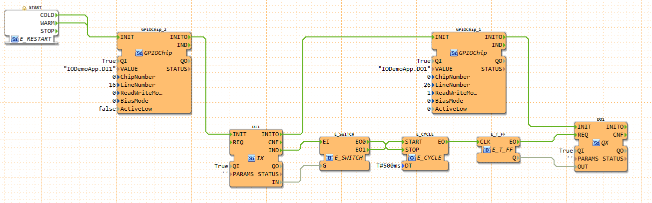
The following picture shows an example application.
The application periodically toggles the output pin 26, while the input pin 16 is high.
You can connect an LED to obtain a blinking light.
 The inputs of the GPIOChip are the following:
| Name | Description |
|---|---|
| VALUE | Receiver IX/QX block name |
| ChipNumber | ID of /dev/gpiochipX device |
| LineNumber | ID of GPIO line within the selected chip |
| ReadWriteMode | Reading/Writing mode of line (0=read, 1=write push/pull, 2=open drain, 3=open source) |
| BiasMode | Bias mode of line (0=none, 1=pull up, 2=pull down) |
| ActiveLow | True if a logic 1 corresponds to low voltage |
To find out the chip- and line number the gpioinfo tool can be used. The VALUE input defines the IO FB to which it is connected. If the IO Block is placed inside an APP: VALUE = App-Name.FB-Name. If it is placed in the Resource: VALUE = App-Name.
Where to go from here?
You can see the supported protocols:
Supported Communication Protocols
You can see the examples:
If you want to go back to the Where to Start page, we leave you here a fast access
Or Go to top